 es
es English
 Русский
 España
 عرب .
عرب .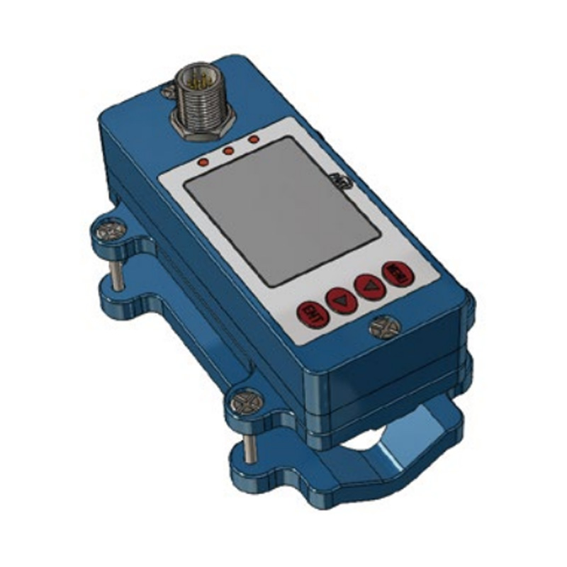
Si necesita ayuda, no dude en contactarnos.
Consultar
Si tiene alguna pregunta adicional, por favor llame al +86-021-37566990 o complete el formulario de consulta.
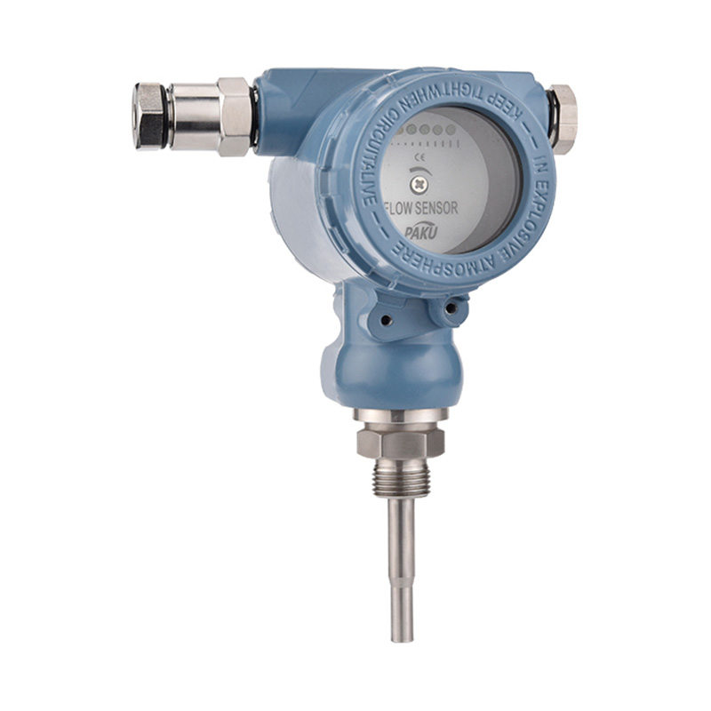
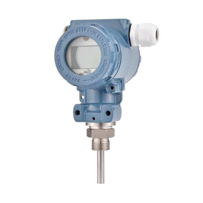
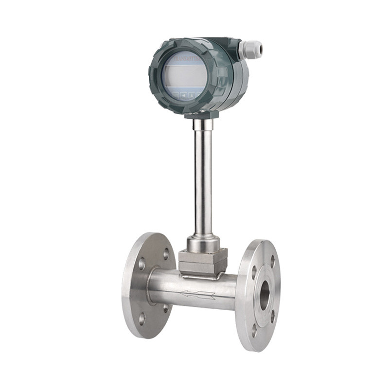
Obtenga cuponesSensor de caudal de vórtice inteligente - SN53
Introducción del producto
El caudalímetro de vórtice serie SN53 es un tipo de caudalímetro de velocidad, diseñado según la teoría de vórtices de Karman, que utiliza el principio de vibración natural del fluido y un cristal piezoeléctrico o un condensador diferencial como elemento de detección.
Este producto emplea una tecnología diferencial única, con aislamiento, blindaje y filtrado, entre otras medidas, para superar las deficiencias de productos similares, como la baja resistencia a los impactos, el ruido, la interferencia de señales débiles, etc. Además, utiliza una carcasa de la sonda de detección con tecnología y medidas de protección innovadoras para garantizar la fiabilidad del producto.
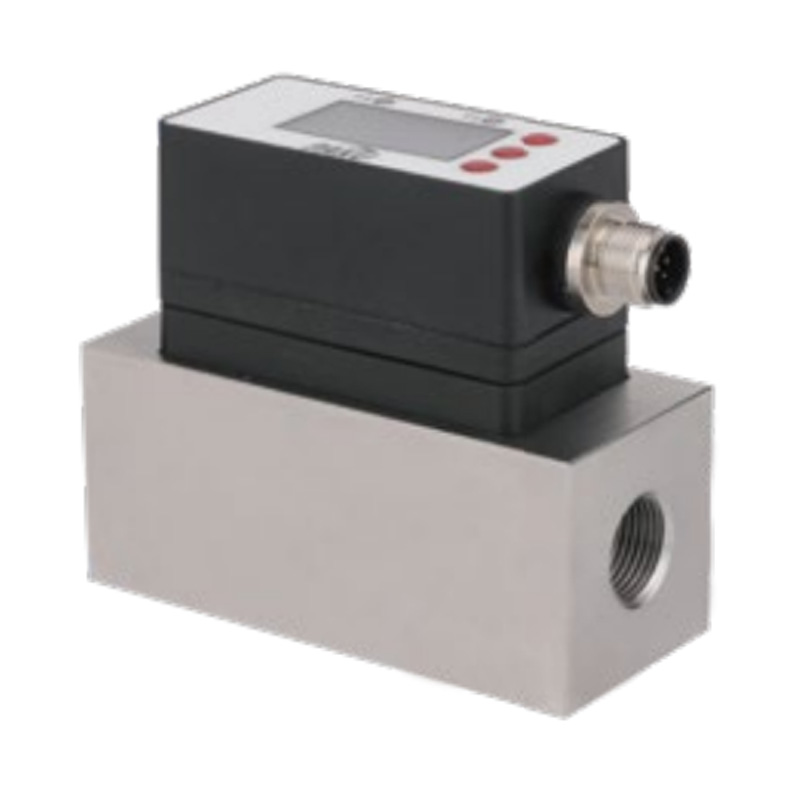
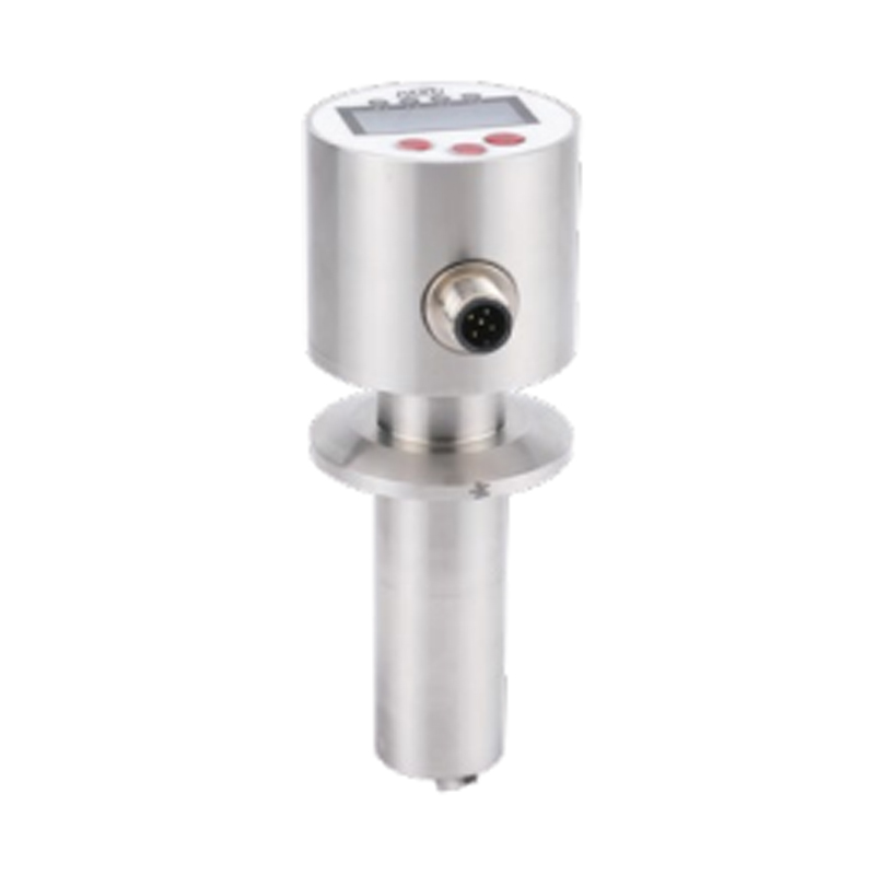
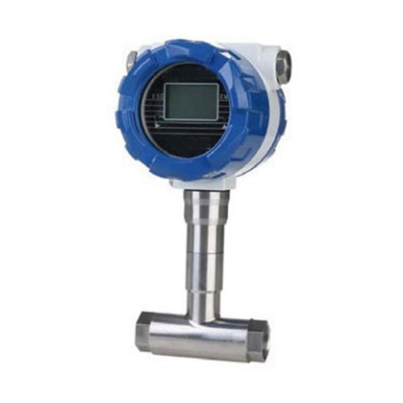
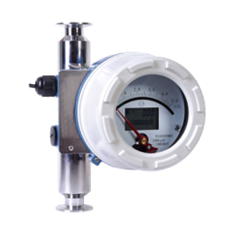
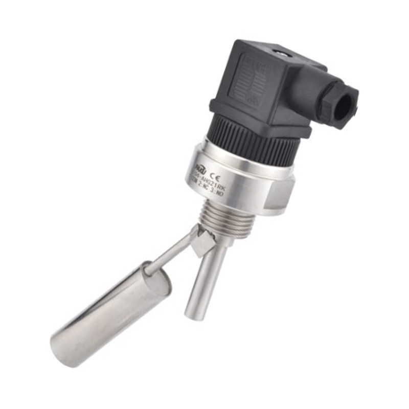
El producto se ofrece en dos versiones: básica y con compensación de temperatura y presión. La versión básica mide la señal de caudal en una sola condición, mientras que la versión con compensación mide simultáneamente la temperatura, la presión y el caudal, y proporciona la salida de caudal volumétrico o de masa estándar tras la compensación. Existen dos tipos de estructura: de tubería y de inserción. Permite la visualización local o la transmisión a larga distancia, y se puede conectar a una red para la gestión centralizada. Se dispone de versiones para altas temperaturas, altas presiones y ambientes explosivos, así como de versiones con estructura modular o monolítica, para adaptarse a diferentes medios y entornos de instalación.
Este producto ofrece una amplia gama de ventajas, como alta precisión, fácil instalación y mantenimiento, y gran adaptabilidad a diversos fluidos. Es idóneo para su uso en las industrias petrolera, química, metalúrgica, de maquinaria, alimentaria, papelera, farmacéutica, de calefacción urbana, de suministro de agua y de gas, entre otras, para la medición de procesos y la gestión energética de una amplia variedad de líquidos, gases, vapor y otros fluidos monofásicos de baja viscosidad.
Descripción técnica
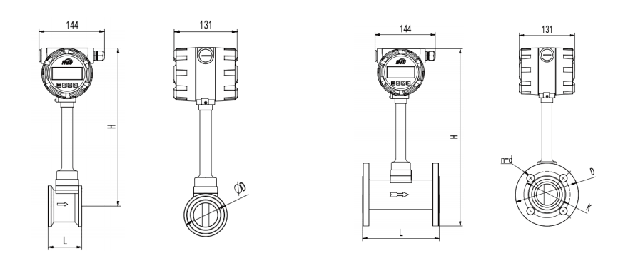
Dibujo de dimensiones
Principio de funcionamiento
Rango de medición
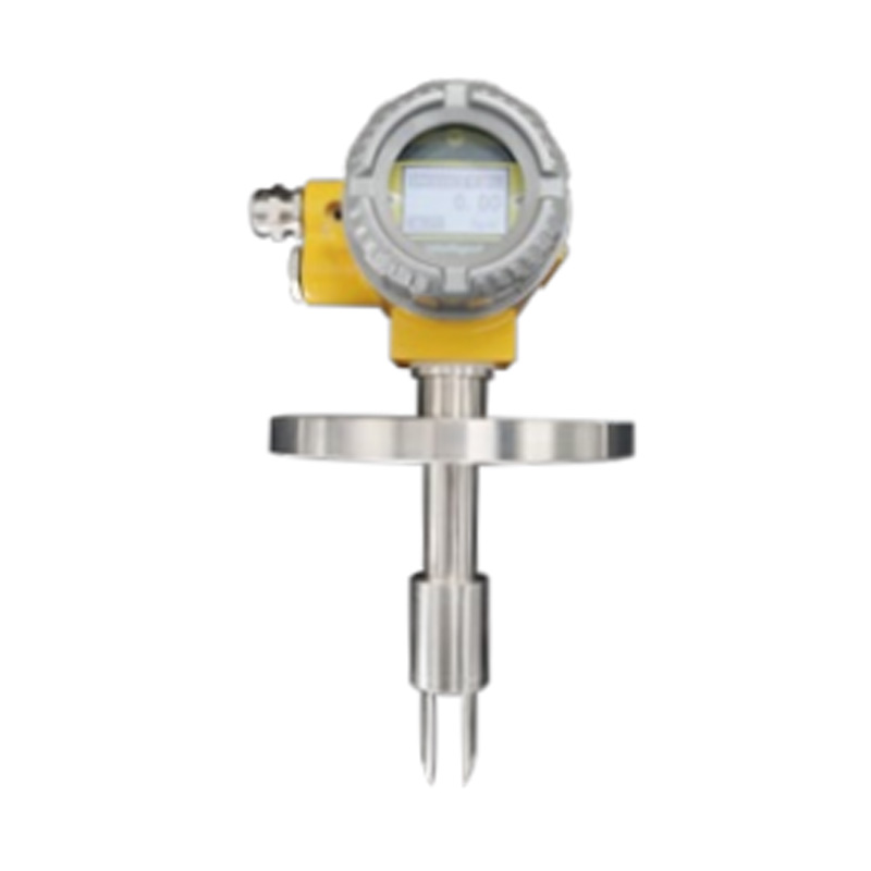
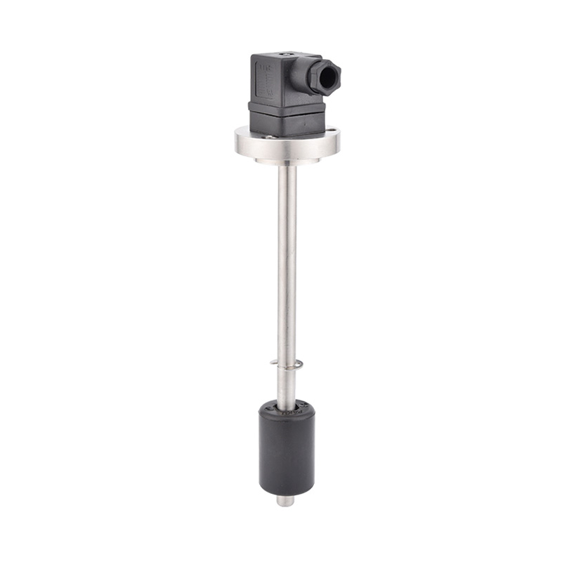
Dibujo dimensional 1 (Tipo de conexión por brida)
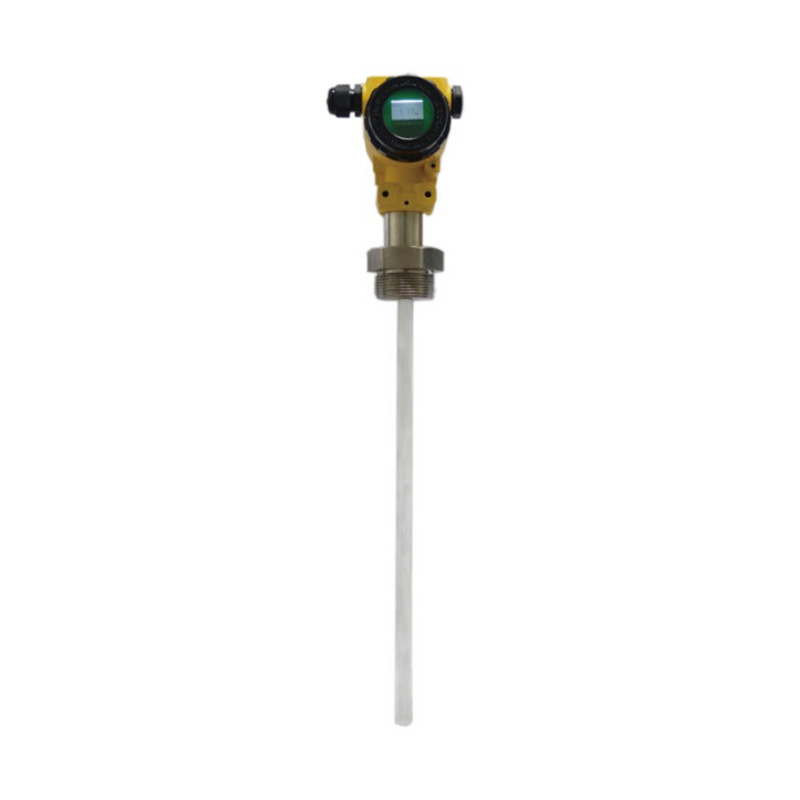
Dibujo con dimensiones 2 (Tipo de fijación con brida)
Tabla de selección
| Calibre | DN15 - DN300 | ||||||||||||||||||||||||||
| Medición de líquidos | Vapor saturado, vapor sobrecalentado, líquido, gas. | ||||||||||||||||||||||||||
| Exactitud | ±1,0, 1,5 (complemento 2,5) | ||||||||||||||||||||||||||
| Repetibilidad de la medición | 0.3 (R) | ||||||||||||||||||||||||||
| Presión nominal | 1,6 MPa, 2,5 MPa, 4,0 MPa y más | ||||||||||||||||||||||||||
| Temperatura del fluido | -40~250 °C (tipo normal), 100~350 °C (tipo de alta temperatura) | ||||||||||||||||||||||||||
| Señal de salida | Salida de pulsos de 3 cables o corriente estándar de 4-20 mA de 2 cables | ||||||||||||||||||||||||||
| Fuente de alimentación | +24 VCC | ||||||||||||||||||||||||||
| Entorno de trabajo | Temperatura -25~60°C | ||||||||||||||||||||||||||
| Humedad | ≤90 HR | ||||||||||||||||||||||||||
Generador de vórtices no lineal (fluido resistivo) en el fluido. A partir del vórtice,
ambos lados del generador de vórtices producen alternativamente dos filas de vórtices regulares, denominados calle de vórtices de Kárman, como se muestra en la Figura (I).
Este tipo de vórtice se denomina calle de vórtices de Kárman, como se muestra en la Figura (I).
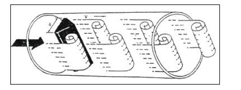
Las columnas de vórtices se disponen asimétricamente aguas abajo del generador de vórtices. Supongamos que la
frecuencia de ocurrencia del vórtice es f, la velocidad promedio del medio medido es V, el generador de vórtices se encuentra con la superficie de flujo,
el ancho del generador de vórtices es d, el diámetro del cuerpo de la mesa es D. Según el principio de la calle de vórtices de Carman, se obtiene la siguiente relación:
f = StV/d
(Ecuación (1))
Donde: f = lado del generador de la frecuencia generada por el vórtice de Kamen,
St = número de Strohal (número adimensional)
V = velocidad promedio de flujo del fluido
d = ancho del generador de vórtices
Se puede observar que, midiendo la frecuencia de separación de los vórtices de Kamen, se puede calcular el caudal instantáneo.
El caudal instantáneo se puede calcular midiendo la frecuencia de separación de las calles de los vórtices de Kamen. El número de Strohal (St) es una incógnita adimensional, y la figura (ii) muestra la
relación entre el número de Strohal (St) y el número de Reynolds (Re).
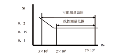
Se puede observar que el flujo instantáneo se puede calcular midiendo la frecuencia de separación del vórtice de Kamen.
El número de Strohal (St) es una incógnita sin factor, y la Figura (II) muestra el número de Strohal (St) en función del número de Reynolds
(Re)
( N = número de pulsos Q = caudal volumétrico (m³)
| Calibre del instrumento (mm) |
Fluidos | Gases | |||||||||||||||||||||||||
| Rango de medición (m³/H) |
Rango de frecuencia de salida (Hz) |
pequeña señal | Rango de medición (m³/H) |
Rango de frecuencia de salida (Hz) | pequeña señal | ||||||||||||||||||||||
| 15 | 0,4 ~4 | 40 ~400 | 15 | 5.0-15 | 280 ~ 1200 | 100 | |||||||||||||||||||||
| 20 | 0,8 ~8 | 33 ~330 | 10 | 6 ~ 30 | 230 ~ 1100 | 80 | |||||||||||||||||||||
| 25 | 1.2~ 12 | 25 ~250 | 8 | 10.0~55 | 200 ~ 1200 | 70 | |||||||||||||||||||||
| 32 | 2.0 ~20 | 20 ~200 | 6 | 12 ~ 120 | 120 ~ 1200 | 60 | |||||||||||||||||||||
| 40 | 3.0~30 | 15 ~ 150 | 6 | 20 a 200 | 100 ~ 1000 | 50 | |||||||||||||||||||||
| 50 | 5.0~ 50 | 13 ~ 130 | 5 | 30 a 300 | 80 ~800 | 40 | |||||||||||||||||||||
| 65 | 8.0 ~80 | 9.7 ~97 | 4 | 50~500 | 60 ~600 | 30 | |||||||||||||||||||||
| 80 | 12~ 120 | 7.7 ~77 | 3 | 80 a 800 | 50 ~500 | 25 | |||||||||||||||||||||
| 100 | 20 a 200 | 6.7 ~67 | 2 | 120 ~ 1200 | 40 ~400 | 20 | |||||||||||||||||||||
| 125 | 30 ~300 | 5.0 ~50 | 2 | 200 ~2000 | 35 ~350 | 20 | |||||||||||||||||||||
| 150 | 40 a 400 | 3.8 ~38 | 1 | 300 a 3000 | 30 ~300 | 15 | |||||||||||||||||||||
| 200 | 75 a 750 | 3.0 ~30 | 1 | 500~ 5000 | 20 a 200 | 10 | |||||||||||||||||||||
| 250 | 110~ 1100 | 2.3 a 23 | 1 | 800~8000 | 16~ 160 | 5 | |||||||||||||||||||||
| 300 | 160~ 1600 | 2.0~20 | 1 | 1100~ 11000 | 13~ 130 | 5 | |||||||||||||||||||||
| Diámetro nominal (mm) |
Tipo de conexión de brida | ||||||||||||||||||||||||||
| Longitud del metro L (mm) |
Altura del medidor H (mm) |
Diámetro exterior de la brida D (mm) |
Espesor de brida C (mm) |
Distancia del orificio del perno K (mm) |
Diámetro del orificio del perno (mm) |
Número de agujeros del perno | Especificación del perno | Especificaciones de tuberías | |||||||||||||||||||
| 25 | 160 | 352 | 115 | 16 | 85 | 14 | 4 | M 12 | Φ32*3,5 | ||||||||||||||||||
| 32 | 160 | 352 | 140 | 18 | 100 | 18 | 4 | M 16 | Φ39*4.5 | ||||||||||||||||||
| 40 | 180 | 345 | 150 | 18 | 110 | 18 | 4 | M 16 | Φ48*4 | ||||||||||||||||||
| 50 | 180 | 350 | 165 | 19 | 125 | 18 | 4 | M 16 | Φ59*4.5 | ||||||||||||||||||
| 65 | 180 | 358 | 185 | 20 | 145 | 18 | 4 | M 16 | Φ74*4.5 | ||||||||||||||||||
| 80 | 180 | 365 | 200 | 20 | 160 | 18 | 8 | M 16 | Φ89*4.5 | ||||||||||||||||||
| 100 | 200 | 375 | 220 | Veintidós | 180 | 18 | 8 | M 16 | Φ 109*4,5 | ||||||||||||||||||
| 125 | 200 | 390 | 250 | Veintidós | 210 | 18 | 8 | M 16 | Φ 134*4,5 | ||||||||||||||||||
| 150 | 200 | 405 | 285 | veinticuatro | 240 | Veintidós | 8 | M 16 | Φ 159*4,5 | ||||||||||||||||||
| 200 | 200 | 430 | 340 | 26 | 295 | Veintidós | 12 | M 16 | Φ219*9 | ||||||||||||||||||
| 250 | 250 | 455 | 405 | 28 | 355 | 26 | 12 | M24 | Φ273*11 | ||||||||||||||||||
| 300 | 460 | 28 | 410 | 26 | 12 | M24 | Φ325*12 | ||||||||||||||||||||
| * El medidor de flujo de turbina tipo conexión de brida no viene con brida de tubería ni pernos, los usuarios deben comprarlos por separado. | |||||||||||||||||||||||||||
| Diámetro nominal (mm) |
Tipo de sujeción de brida | ||||||||||||||||||||||||||
| Longitud del metro L (mm) |
Longitud de instalación L (mm) |
Altura del medidor H (mm) |
Diámetro exterior de la cara del extremo D(mm) |
Especificaciones de tuberías | |||||||||||||||||||||||
| 15 | 70 | 106 | 381 | 55 | Φ18*1,5 | ||||||||||||||||||||||
| 20 | 70 | 106 | 381 | 55 | Φ25*2,5 | ||||||||||||||||||||||
| 25 | 70 | 106 | 381 | 55 | Φ32*3,5 | ||||||||||||||||||||||
| 32 | 70 | 106 | 381 | 55 | Φ39*3.5 | ||||||||||||||||||||||
| 40 | 85 | 121 | 381 | 80 | Φ49*4.5 | ||||||||||||||||||||||
| 50 | 85 | 121 | 391 | 90 | Φ59*4.5 | ||||||||||||||||||||||
| 65 | 85 | 121 | 405 | 105 | Φ74*4.5 | ||||||||||||||||||||||
| 80 | 85 | 116 | 420 | 120 | Φ89*4.5 | ||||||||||||||||||||||
| 100 | 85 | 118 | 440 | 140 | Φ109*4.5 | ||||||||||||||||||||||
| 125 | 90 | 124 | 465 | 168 | Φ134*4.5 | ||||||||||||||||||||||
| 150 | 102 | 135 | 492 | 192 | Φ159*4.5 | ||||||||||||||||||||||
| 200 | 102 | 150 | 548 | 248 | Φ219*9 | ||||||||||||||||||||||
| 250 | 115 | 166 | 605 | 300 | Φ273*11 | ||||||||||||||||||||||
| 300 | 130 | 185 | 651 | 350 | Φ325*12 | ||||||||||||||||||||||
| * Los parámetros anteriores son aplicables al medidor de caudal tipo vórtice con conexión de brida con clase de resistencia a la presión de 1,6 MPa. | |||||||||||||||||||||||||||
| SN53- | 1 | A | 025 | C | 2 | 2B | 2 | 0 | A | 1 | D | Descripción detallada | |||||||||||||||
| SN53- | Sensor de flujo Vortex serie SN53 | ||||||||||||||||||||||||||
| Método de conexión | 1 | Tipo de conexión de brida | |||||||||||||||||||||||||
| 2 | Tipo de sujeción | ||||||||||||||||||||||||||
| 3 | Tipo de inserción | ||||||||||||||||||||||||||
| 4 | Tipo de abrazadera | ||||||||||||||||||||||||||
| Medio | A | Líquido | |||||||||||||||||||||||||
| B | Gas general | ||||||||||||||||||||||||||
| C | Vapor saturado (se recomienda compensación de temperatura y presión) | ||||||||||||||||||||||||||
| D | Vapor sobrecalentado (se recomienda compensación de temperatura y presión) | ||||||||||||||||||||||||||
| Una vía pública | 025 | Para las opciones de calibre, 025 representa una tubería DN25 (para tuberías especiales (consulte al ingeniero de ventas para diámetros especiales) |
|||||||||||||||||||||||||
| Compresivo | B | 1,6 MPa | |||||||||||||||||||||||||
| C | 2,5 MPa | ||||||||||||||||||||||||||
| D | 4,0 MPa | ||||||||||||||||||||||||||
| F | Otros | ||||||||||||||||||||||||||
| Temperatura de funcionamiento | 1 | Tipo ordinario: -20-100℃ | |||||||||||||||||||||||||
| 2 | Tipo de temperatura media: 100-250 ℃ | ||||||||||||||||||||||||||
| 3 | Tipo de alta temperatura: 250-350 ℃ | ||||||||||||||||||||||||||
| Material del cuerpo | 1 | Acero inoxidable 304 | |||||||||||||||||||||||||
| 2 | Acero inoxidable 316L | ||||||||||||||||||||||||||
| Material de la brida | A | Acero carbono | |||||||||||||||||||||||||
| B | Acero inoxidable 304 | ||||||||||||||||||||||||||
| C | Acero inoxidable 316L | ||||||||||||||||||||||||||
| Señal de salida | 1 | Pantalla local, salida de señal de pulso | |||||||||||||||||||||||||
| 2 | Pantalla local, salida analógica de 4-20 mA | ||||||||||||||||||||||||||
| 3 | Sin pantalla local, salida de señal de pulso | ||||||||||||||||||||||||||
| 4 | Sin pantalla local, salida analógica de 4-20 mA | ||||||||||||||||||||||||||
| Método de comunicación | 0... | 0: Sin comunicación 1: Comunicación RS485 2: Comunicación HART |
|||||||||||||||||||||||||
| Tipo de convertidor | A | Tipo integral | |||||||||||||||||||||||||
| B | Tipo dividido: Cuerpo del medidor separado | ||||||||||||||||||||||||||
| C | Tipo dividido: totalizador de flujo sin caja de medidor | ||||||||||||||||||||||||||
| D | Procesador digital (opcional) | ||||||||||||||||||||||||||
| Requisitos a prueba de explosiones | 1... | 1: Tipo normal 2: Tipo a prueba de explosiones | |||||||||||||||||||||||||
| Método de suministro de energía | D... | D:24 V A:24 V + fuente de alimentación de batería C:fuente de alimentación de batería | |||||||||||||||||||||||||
| Método de compensación | 1 | No | |||||||||||||||||||||||||
| 2 | Compensación de temperatura | ||||||||||||||||||||||||||
| 3 | Compensación de presión | ||||||||||||||||||||||||||
| 4 | Compensación de temperatura y presión al mismo tiempo | ||||||||||||||||||||||||||
| * La tabla de selección es solo para la selección de parámetros y se envía con el código correspondiente al parámetro. | |||||||||||||||||||||||||||
Shanghai Kayuan Electronic
Technology Co., Ltd.
Technology Co., Ltd.
Shanghai Kayuan Electronic Technology Co., Ltd. es una empresa especializada en la producción e investigación y desarrollo (I+D) de sensores y controladores de fluidos industriales. Nuestros productos principales incluyen interruptores y sensores para medición de flujo, presión, temperatura y nivel de líquidos.
En el año 2008, establecimos nuestra planta de ensamblaje en Shanghái, China, para fabricar la serie de productos de PAKU. Adoptamos tecnología avanzada y procesos de fabricación modernos en todas nuestras operaciones. Gracias a nuestra tecnología de diseño y producción profesional, completa gama de productos, excelente calidad y red de servicios de ventas, podemos ofrecer a los usuarios no solo soporte técnico profesional y oportuno, sino también servicios integrales de alta calidad.
La empresa ha establecido diversos departamentos, como compras, I+D, gestión de calidad, finanzas, ventas, servicio postventa, oficina general, laboratorio, sala de archivo, taller de calibración, taller de producción, área de inspección, zona de almacenamiento, área de envío y una sala de descanso para tomar té, con el objetivo de proporcionar productos de excelente calidad y servicios sinceros.
Adherimos al concepto centrado en el cliente de crear valor para los mismos. De acuerdo con las necesidades del sector industrial de nuestros clientes, actualizamos continuamente nuestra tecnología y optimizamos nuestros servicios, con la visión de convertirnos en líderes en el campo de la automatización de procesos.
Los productos de PAKU se utilizan ampliamente en diversas industrias, incluyendo equipos completos de automatización, equipos petroleros, equipos químicos, equipos eléctricos, equipos de soldadura, equipos siderúrgicos, equipos metalúrgicos, industria automotriz y tratamiento de aguas. Hemos servido a numerosos clientes tanto nacionales como internacionales, y nuestros productos se exportan a países como Canadá, Estados Unidos, Brasil, Indonesia, Vietnam, Tailandia y Rusia.
En el cada vez más competitivo mercado global del futuro, PAKU continuará sirviendo, como siempre lo ha hecho, a una amplia gama de clientes nacionales e internacionales con calidad excepcional, precios razonables y competitivos, entregas puntuales y un servicio postventa perfecto. Damos la bienvenida a una amplia cooperación con clientes OEM (fabricantes de equipos originales) y ODM (fabricantes de diseño original).

Información
 [email protected]
![]() +86-13386111894 / +86-021-37566990
+86-13386111894 / +86-021-37566990
![]() 4º piso, No. 3, Callejón 1313, Calle Nanting, Distrito de Fengxian, Shanghai, China
4º piso, No. 3, Callejón 1313, Calle Nanting, Distrito de Fengxian, Shanghai, China

Enlaces de Productos