 es
es English
 Русский
 España
 عرب .
عرب .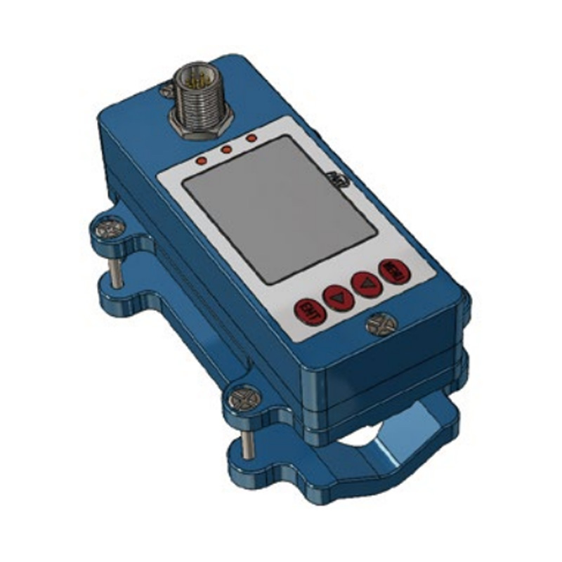
Si necesita ayuda, no dude en contactarnos.
Consultar
Si tiene alguna pregunta adicional, por favor llame al +86-021-37566990 o complete el formulario de consulta.
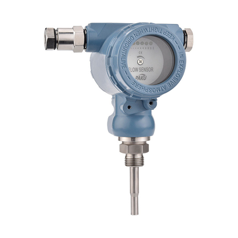
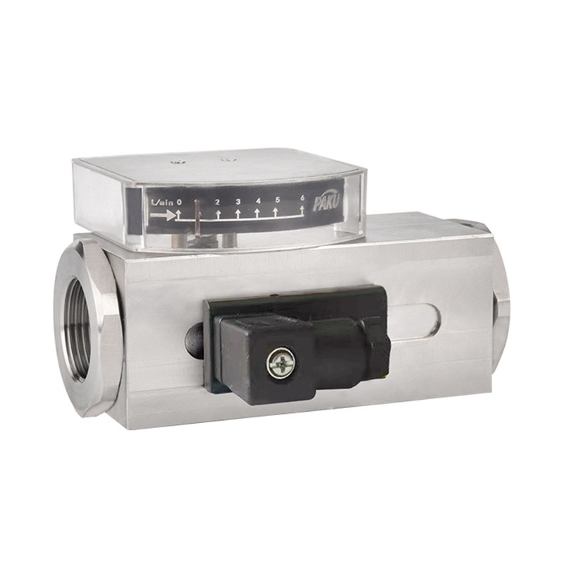
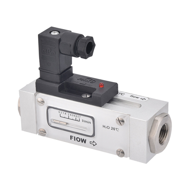
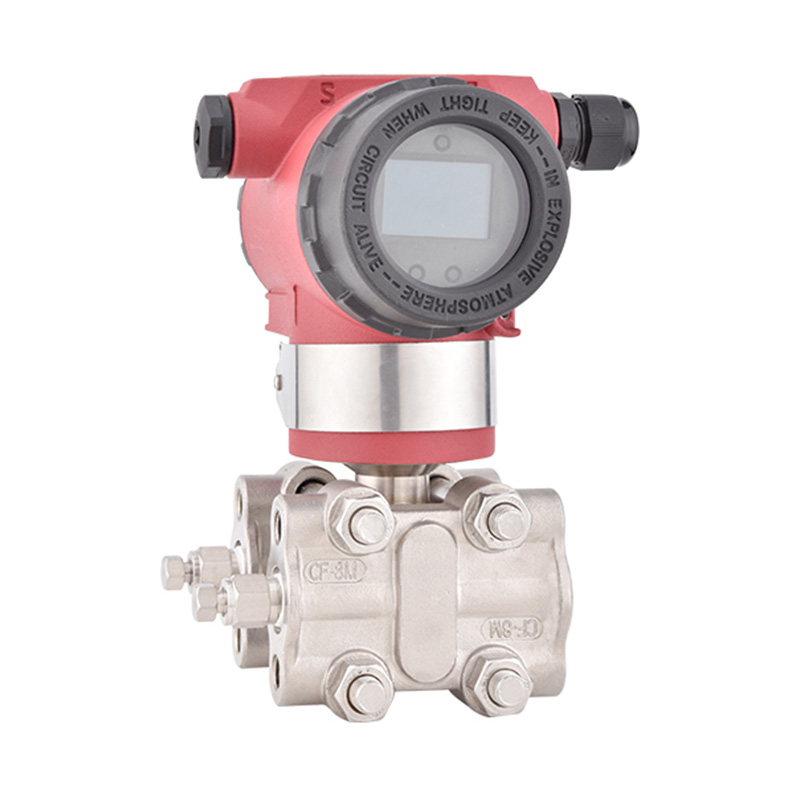
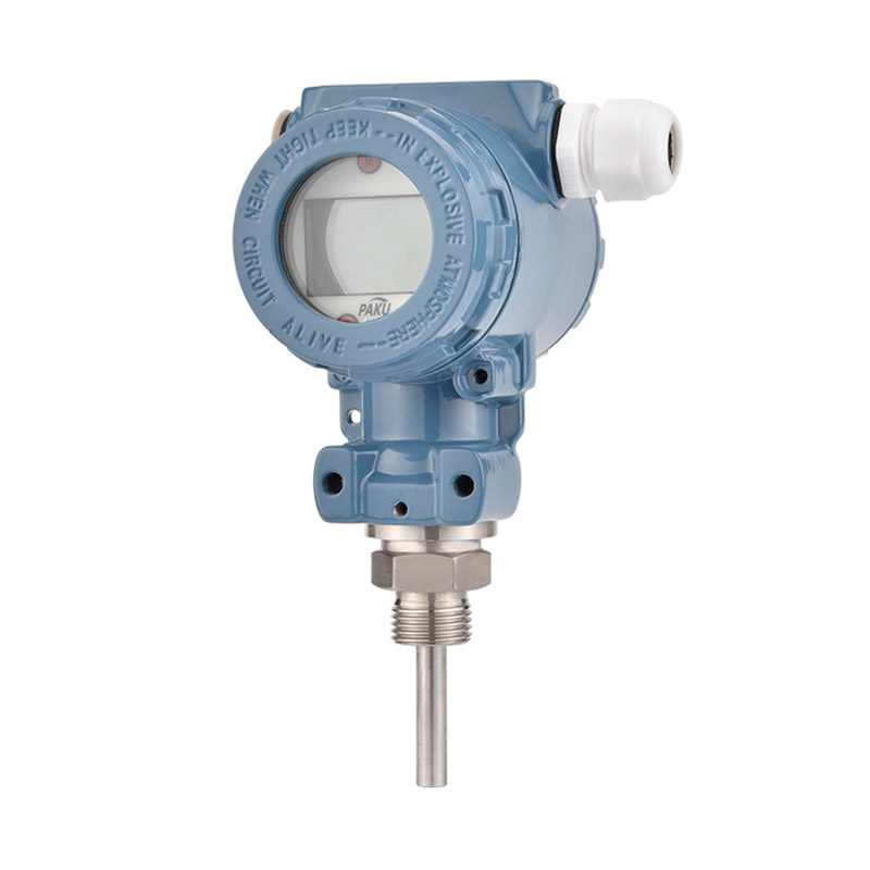
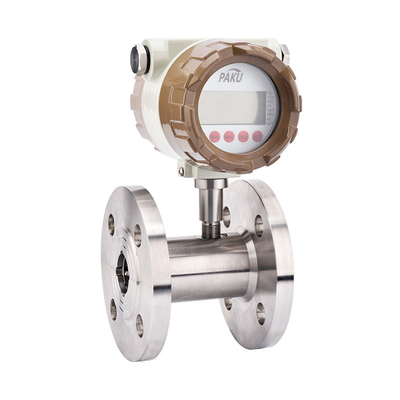
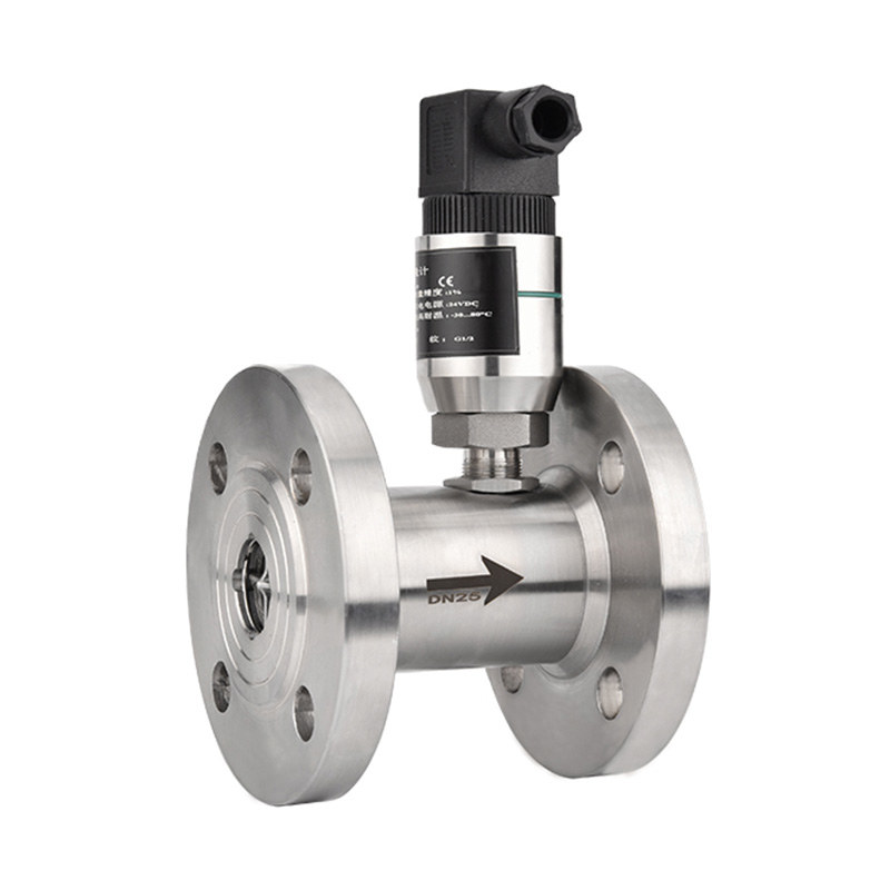
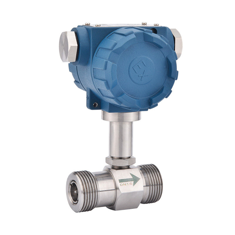
Obtenga cuponesSensor de Flujo de Turbina – SN51
Introducción del producto
SN51 series turbine flow sensor is a precision flow measuring instrument. It absorbs advanced technology of domestic and foreign flow instruments and has been optimized and designed. It has a simple structure, lightweight and
It has high accuracy, good reproducibility, sensitive response, easy installation, maintenance and use, and is suitable for measuring low viscosity media such as water, diesel, gasoline, etc. Compatibility with corresponding traffic
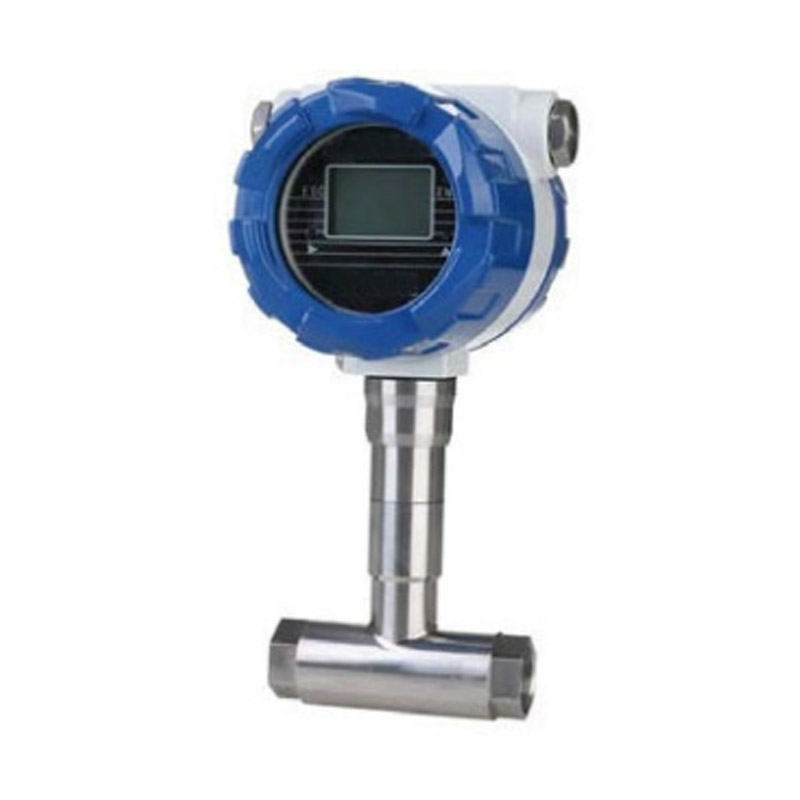
The instrument case matching can be used to measure the flow rate and total amount of liquid. Widely used in computing and control systems in petroleum, chemical industry, metallurgy, scientific research and other fields.
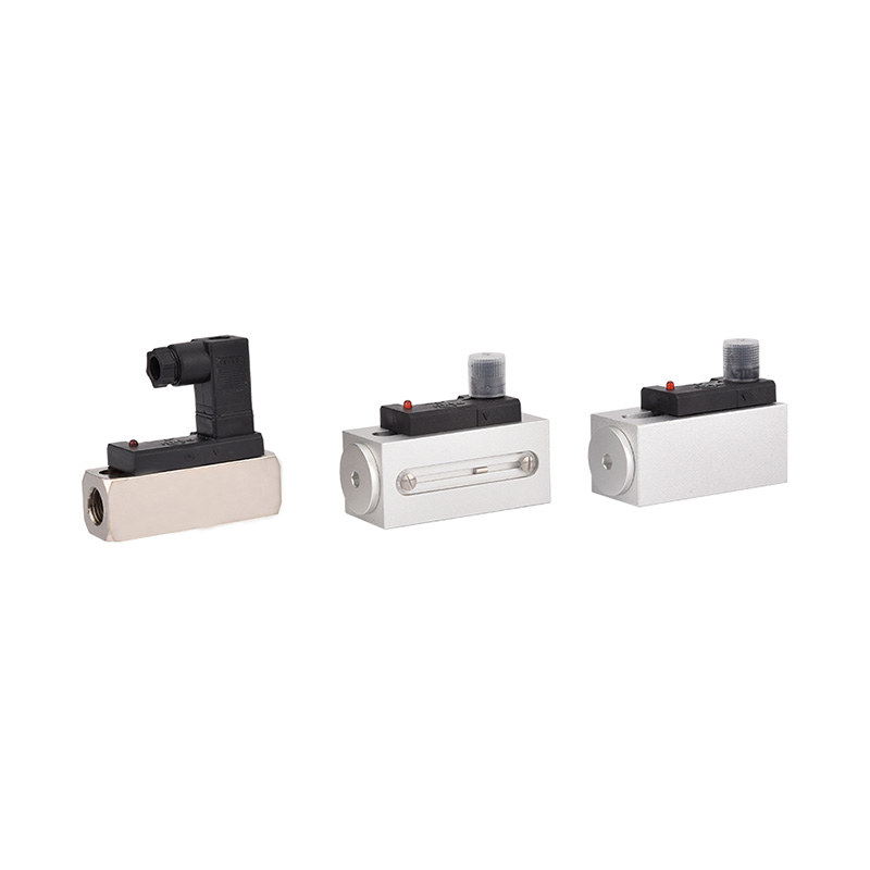
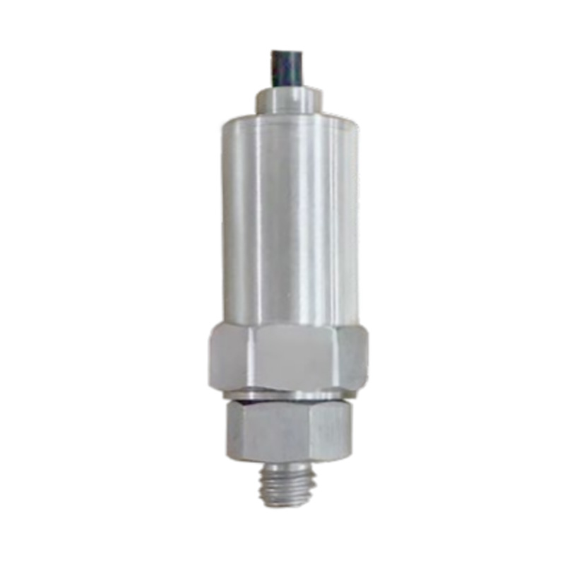
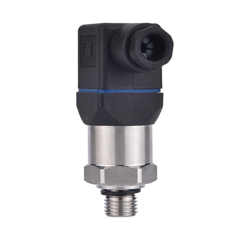
Sensors are available in various forms such as ordinary type, high-precision type and wear-resistant type (cemented carbide). There are two types of amplifiers: ordinary type and explosion-proof type, and the sensor can also be calculated with on-site flow.
The meter is equipped with (powered by lithium batteries, battery replacement in 1 year).
Tabla de parámetros
Dibujo de dimensiones
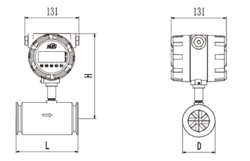
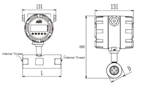
Dimensiones 1 (Tipo de fijación con clip)
Dimensiones (Figura 2: Tipo de conexión roscada)
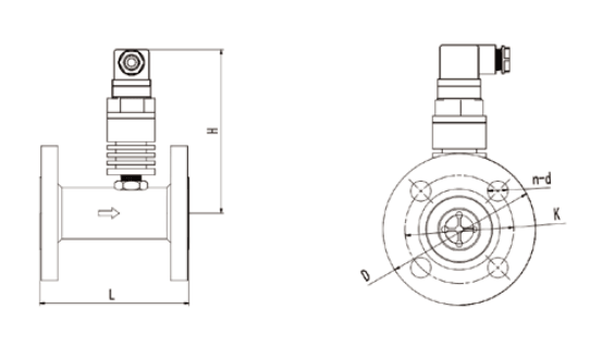
Dimensiones (Figura 3: tipo de conexión con brida PN16)
Imagen
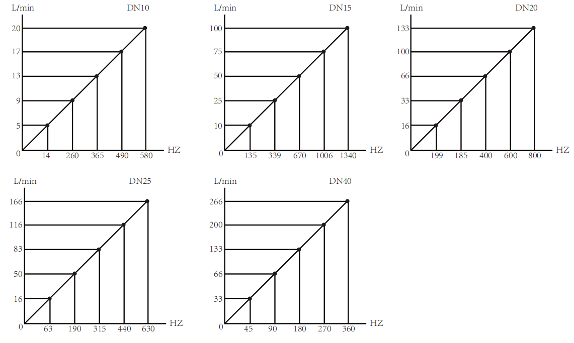
Gráfico de curva
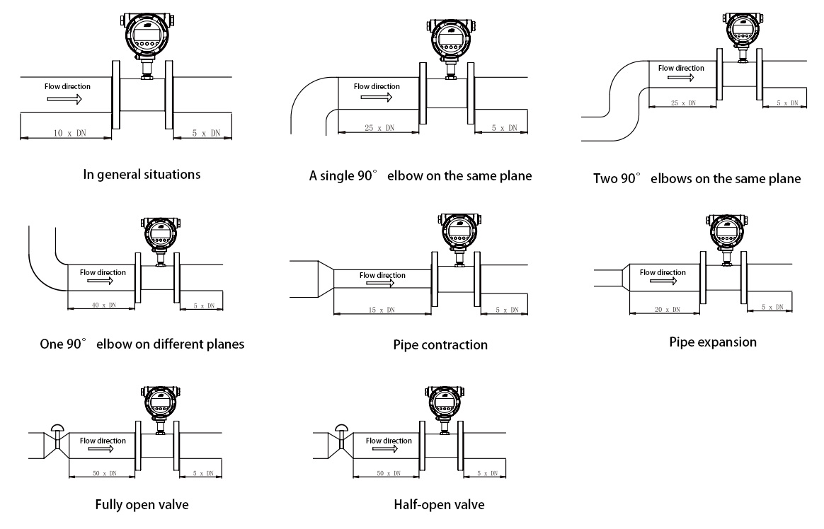
Requisitos de instalación para secciones de tubería rectas
Tabla de selección
| Diámetro llamado DN (mm) |
Rango de caudal (m³/H) | Presión nominal PN (MPa) |
Pérdida máxima de presión (MPa) |
|||||||||||||||||||||||||||||||||
| Límite inferior | Límite superior | Límite inferior | Límite superior | Límite inferior | Límite superior | |||||||||||||||||||||||||||||||
| 2 | 0.03 | 0.16 | Resistencia a la presión de la rosca: 6,3 Resistencia a la presión de la novia: 1,6 Indica la resistencia a la presión especial |
0,15 | ||||||||||||||||||||||||||||||||
| 4 | 0.04 | 0,25 | 0.12 | |||||||||||||||||||||||||||||||||
| 6 | 0.1 | 0.6 | 0.08 | |||||||||||||||||||||||||||||||||
| 10 | 0.2 | 1.2 | 0.05 | |||||||||||||||||||||||||||||||||
| 12 | 0.12 | 2.4 | 0.05 | |||||||||||||||||||||||||||||||||
| 15 | 0.6 | 4 | 0.6 | 6 | 0.035 | |||||||||||||||||||||||||||||||
| 20 | 0.8 | 8 | ||||||||||||||||||||||||||||||||||
| 25 | 1.6 | 10 | 1 | 10 | ||||||||||||||||||||||||||||||||
| 32 | 1.5 | 15 | ||||||||||||||||||||||||||||||||||
| 40 | 3 | 20 | 3 | 20 | 2 | 20 | 0.025 | |||||||||||||||||||||||||||||
| 50 | 6 | 40 | 6 | 40 | 4 | 40 | ||||||||||||||||||||||||||||||
| 65 | 8 | 80 | ||||||||||||||||||||||||||||||||||
| 80 | 16 | 100 | 16 | 100 | 10 | 100 | ||||||||||||||||||||||||||||||
| 100 | 25 | 160 | 25 | 160 | 20 | 222 | ||||||||||||||||||||||||||||||
| 125 | 25 | 250 | ||||||||||||||||||||||||||||||||||
| 150 | 60 | 400 | 50 | 300 | 40 | 400 | ||||||||||||||||||||||||||||||
| 200 | 100 | 600 | 80 | 800 | ||||||||||||||||||||||||||||||||
| 250 | 160 | 1000 | 120 | 1200 | ||||||||||||||||||||||||||||||||
| 300 | 260 | 1600 | 180 | 1800 | ||||||||||||||||||||||||||||||||
| Nota: La columna más a derecha del rango de flujo es valor de referencia estándar y otros rangos de flujo son rangos personalizados. | ||||||||||||||||||||||||||||||||||||
Tipo de ajuste por clip
Tipo de conexión de novia
| Diámetro del instrumento (mm) |
Largo (mm ) | Diámetro (mm) |
Mmm) | |||||||||||||||||||||||||||||||||
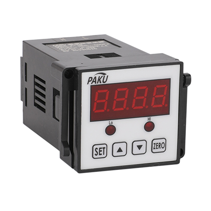
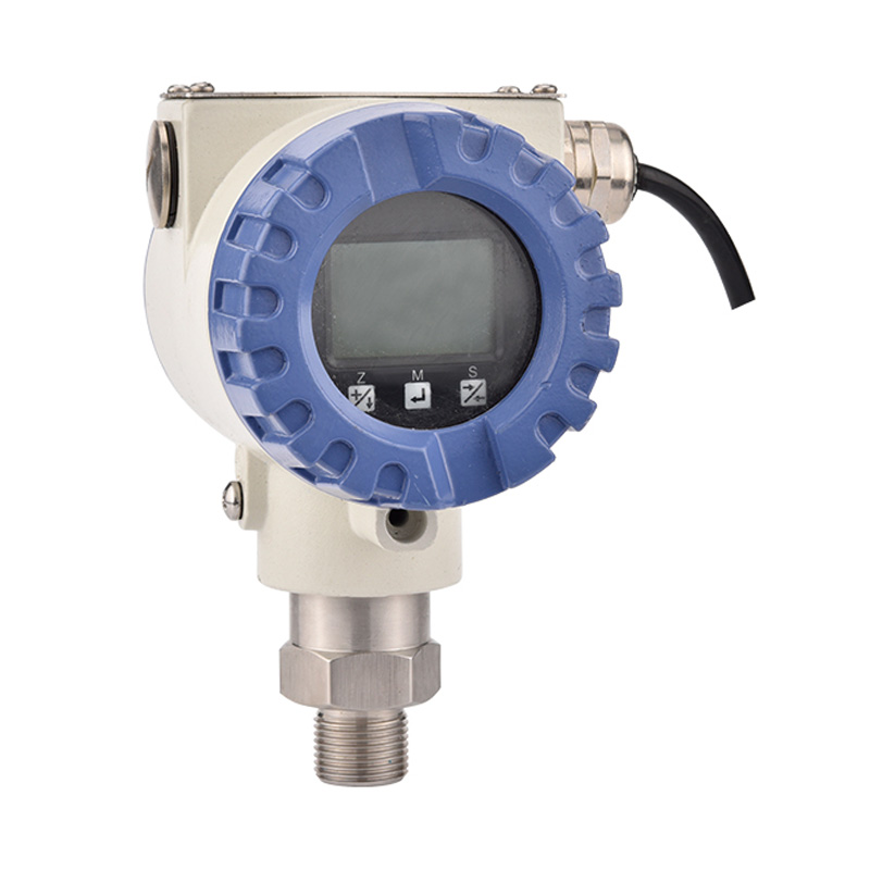
| Tipo de pulso | Tipo de pulso a prueba de explosiones | Tipo de salida de 4-20 mA | Pantalla inteligente | |||||||||||||||||||||||||||||||||
| 15 | 66 | 66 | 155 | 220 | ||||||||||||||||||||||||||||||||
| 20 | 66 | 66 | 160 | 225 | ||||||||||||||||||||||||||||||||
| 25 | 66 | 66 | 165 | 230 | ||||||||||||||||||||||||||||||||
| 32 | 70 | 86 | 170 | 240 | ||||||||||||||||||||||||||||||||
| 40 | 75 | 86 | 180 | 245 | ||||||||||||||||||||||||||||||||
| 50 | 75 | 92 | 195 | 260 | ||||||||||||||||||||||||||||||||
| 65 | 75 | 105 | 205 | 210 | 210 | 275 | ||||||||||||||||||||||||||||||
| 80 | 84 | 120 | 220 | 225 | 225 | 290 | ||||||||||||||||||||||||||||||
| 100 | 90 | 140 | 245 | 250 | 250 | 310 | ||||||||||||||||||||||||||||||
| 125 | 100 | 165 | 270 | 275 | 275 | 340 | ||||||||||||||||||||||||||||||
| 200 | 150 | 240 | 350 | 350 | 350 | 415 | ||||||||||||||||||||||||||||||
Calibre del medidor mm |
Rosca externa L mm |
Rosca interna L mm |
Mmm) | Rosca externa G |
Rosca interna G |
||||||||||||||||||
| Tipo de pulso | Tipo de pulso a prueba de explosiones |
Tipo de salida de 4-20 mA |
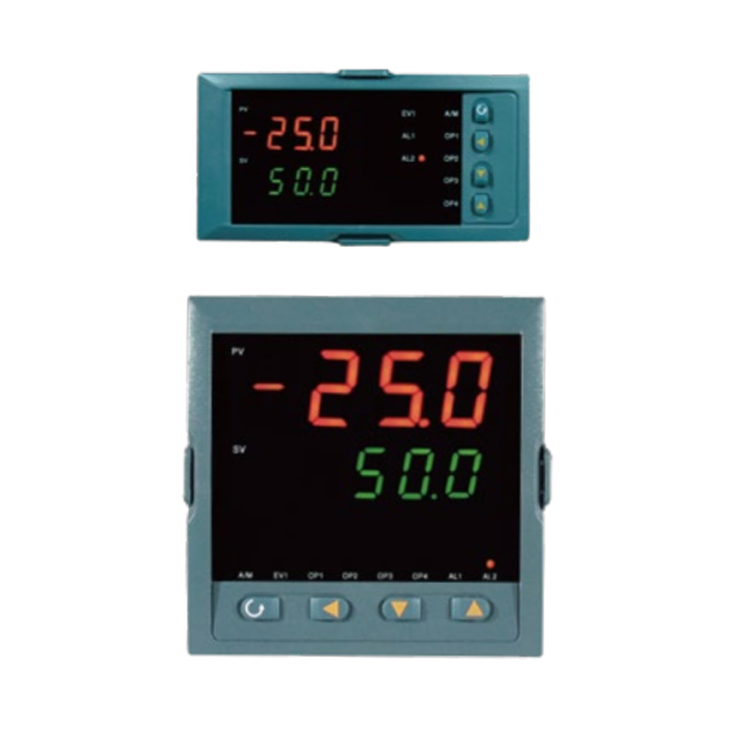
Tipo de pantalla inteligente |
||||||||||||||||||||
| 4 | 225 | 80 | 142 | 145 | 145 | 210 | G1/2 | G1/4 | |||||||||||||||
| 6 | 225 | 80 | 143 | 145 | 145 | 210 | G1/2 | G1/4 | |||||||||||||||
| 8 | 225 | 80 | 144 | 146 | 146 | 210 | G1/2 | G1/4 | |||||||||||||||
| 10 | 345 | 80 | 145 | 150 | 147 | 210 | G1/2 | G3/8 | |||||||||||||||
| 12 | 345 | 80 | 146 | 150 | 1448 | 212 | G3/4 | G1/2 | |||||||||||||||
| 15 | 75 | 110 | 147 | 150 | 150 | 215 | G1 | G1/2 | |||||||||||||||
| 20 | 85 | 115 | 150 | 155 | 155 | 220 | G1 | G3/4 | |||||||||||||||
| 25 | 100 | 140 | 155 | 160 | 160 | 225 | G1-1/4 | G1 | |||||||||||||||
| 32 | 120 | 168 | 175 | 180 | 180 | 245 | G1-1/2 | G1-1/4 | |||||||||||||||
| 40 | 140 | 180 | 180 | 184 | 180 | 250 | G2 | G1-1/2 | |||||||||||||||
| 50 | 150 | 200 | 185 | 190 | 190 | 255 | G2-1/2 | G2 | |||||||||||||||
| Nota: El sensor de flujo DN4-DN10 anterior incluye el tamaño de sección de tubería recta estándar de fábrica, el sensor de flujo de diámetro DN15-DN50 no incluye el tamaño de sección de tubería recta. |
|||||||||||||||||||||||
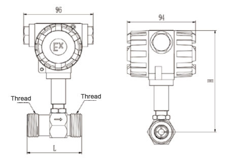
Dimensiones Figura 2 (Tipo de conexión de rosca interna)
Calibre del medidor mm |
Largo mm |
D mm |
K mm |
Mmm) | re mm |
n Número de agujeros |
Resistencia a la presión estándar |
|||||||||||||||||
| Tipo de pulso | Tipo de pulso a prueba de explosiones |
Tipo de salida de 4-20 mA |
Tipo de pantalla inteligente |
|||||||||||||||||||||
| 15 | 75 | 95 | 65 | 175 | 180 | 180 | 245 | 14 | 4 | 1,6 MPa |
||||||||||||||
| 20 | 85 | 105 | 75 | 185 | 190 | 190 | 255 | 14 | 4 | |||||||||||||||
| 25 | 100 | 115 | 85 | 200 | 195 | 195 | 260 | 14 | 4 | |||||||||||||||
| 32 | 120 | 140 | 100 | 210 | 215 | 215 | 275 | 18 | 4 | |||||||||||||||
| 40 | 140 | 150 | 110 | 195 | 220 | 220 | 285 | 18 | 4 | |||||||||||||||
| 50 | 150 | 165 | 125 | 230 | 235 | 235 | 295 | 18 | 4 | |||||||||||||||
| 65 | 175 | 185 | 145 | 255 | 260 | 260 | 325 | 18 | 8 | |||||||||||||||
| 80 | 200 | 200 | 160 | 260 | 265 | 265 | 330 | 18 | 8 | |||||||||||||||
| 100 | 220 | 220 | 180 | 285 | 285 | 285 | 350 | 18 | 8 | |||||||||||||||
| 125 | 250 | 250 | 210 | 310 | 315 | 315 | 380 | 18 | 8 | |||||||||||||||
| 150 | 300 | 285 | 240 | 345 | 345 | 345 | 410 | Veintidós | 8 | |||||||||||||||
| 200 | 360 | 340 | 295 | 395 | 400 | 400 | 465 | Veintidós | 12 | |||||||||||||||
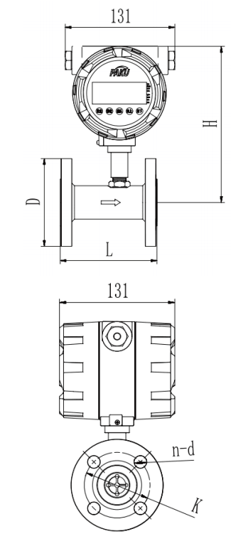
Diagrama de cableado de salida de pulsos

Diagrama de estructura básica del convertidor

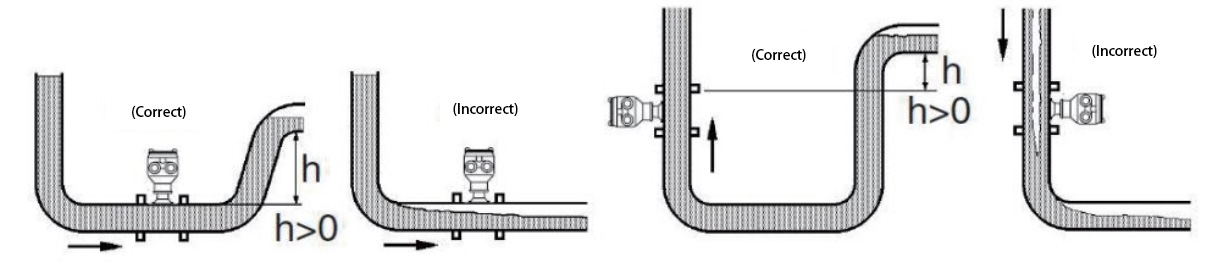
Ubicación de la instalación
| SN51- | 025 | D | 1 | A | P1 | A | D | Descripción detallada | ||||||||||||||||||||||||||||
| SN51- | Sensor de flujo de turbina SN51 | |||||||||||||||||||||||||||||||||||
| SN-51A | Tipo A: Nivel de protección IP67 (Grado de explosión CT6) | |||||||||||||||||||||||||||||||||||
| SN-51B | Tipo B: Nivel de protección IP67 (Grado de explosión CT6) | |||||||||||||||||||||||||||||||||||
| SN51-C | Tipo C: Nivel de protección IP65 | |||||||||||||||||||||||||||||||||||
| 025 | Ejemplo: "025" representa la tubería DN25 |
|||||||||||||||||||||||||||||||||||
| A | Pantalla local alimentada por batería (sin salida) | |||||||||||||||||||||||||||||||||||
| B | Salida de señal de pulso (sin pantalla) (NPN o PNP) | |||||||||||||||||||||||||||||||||||
| C | Salida analógica 4–20mA (sin pantalla) | |||||||||||||||||||||||||||||||||||
| D | Pantalla local + Salida analógica 4–20mA | |||||||||||||||||||||||||||||||||||
| E | Pantalla local + Salida analógica 2–10V | |||||||||||||||||||||||||||||||||||
| F | Pantalla local + Salida analógica 1–5V | |||||||||||||||||||||||||||||||||||
| G | Pantalla local + Salida de señal de pulso (NPN o PNP) | |||||||||||||||||||||||||||||||||||
| 1 | Comunicación RS485 | |||||||||||||||||||||||||||||||||||
| 2 | Protocolo HART | |||||||||||||||||||||||||||||||||||
| 1 | Conexión roscada interna sellada (para DN ≤ 32) | |||||||||||||||||||||||||||||||||||
| 2 | Conexión de novia (para DN ≥ 15) | |||||||||||||||||||||||||||||||||||
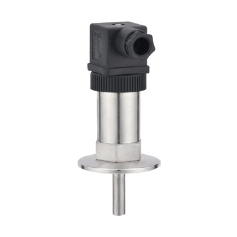
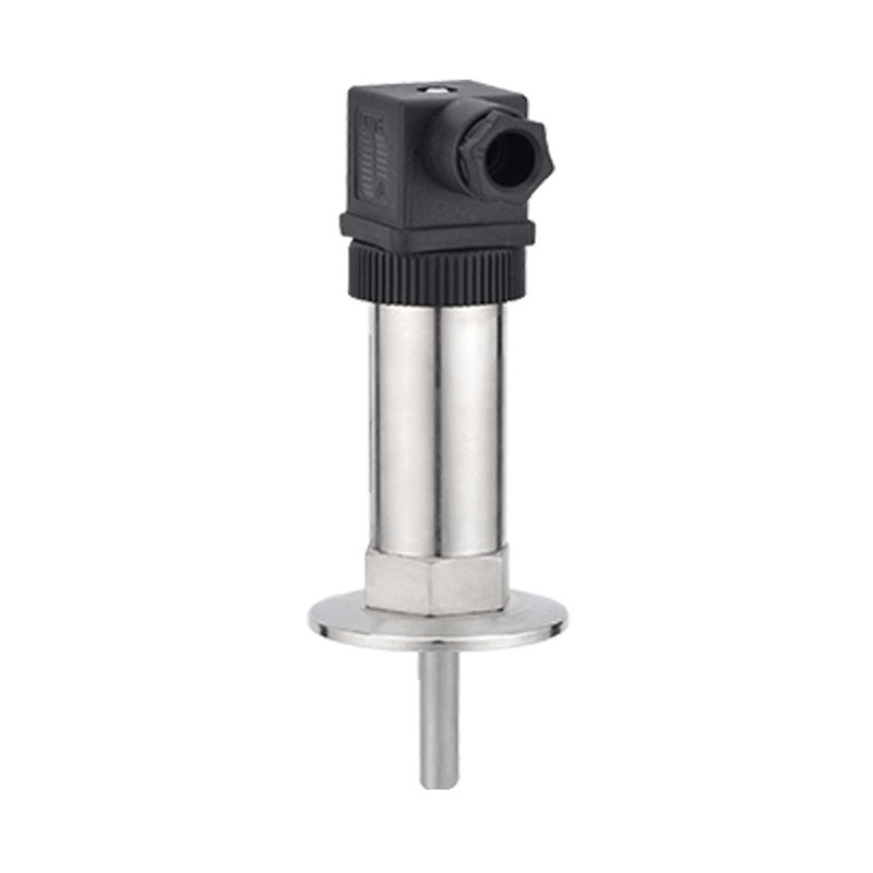
| 3 | Conexión de abrazadera sanitaria | |||||||||||||||||||||||||||||||||||
| 4 | Conexión rápida de manguera | |||||||||||||||||||||||||||||||||||
| 5 | Conexión roscada externa sellada (para DN ≤ 32) | |||||||||||||||||||||||||||||||||||
| C | Opciones de precisión 1.0% | |||||||||||||||||||||||||||||||||||
| P1 | Oportunidades de Resistencia a Presión: 16bar | |||||||||||||||||||||||||||||||||||
| P2 | Oportunidades de Resistencia a Presión: 25bar | |||||||||||||||||||||||||||||||||||
| P3 | Oportunidades de Resistencia a Presión: 40bar | |||||||||||||||||||||||||||||||||||
| P4 | Oportunidades de Resistencia a Presión: 63bar | |||||||||||||||||||||||||||||||||||
| P5 | Oportunidades de Resistencia a Presión: 160 bar (para DN ≤ 50) | |||||||||||||||||||||||||||||||||||
| P6 | Oportunidades de Resistencia a Presión: 250 bar (para DN ≤ 50) | |||||||||||||||||||||||||||||||||||
| P7 | Oportunidades de Resistencia a Presión: 320 bar (para DN ≤ 50) | |||||||||||||||||||||||||||||||||||
| P8 | Oportunidades de Resistencia a Presión: 400 bar (para DN ≤ 50) | |||||||||||||||||||||||||||||||||||
| A | Convertidor de código de pulso (opcional) | |||||||||||||||||||||||||||||||||||
| C | Convertidor inteligente (opcional) | |||||||||||||||||||||||||||||||||||
| D | 24 V | |||||||||||||||||||||||||||||||||||
| A | 220 V | |||||||||||||||||||||||||||||||||||
| C | Batería (solo para modelos sin salida) | |||||||||||||||||||||||||||||||||||
|
* Especifique la dirección del flujo, el tipo de medio, el diámetro de la tubería y el rango de medición de flujo deseado al realizar el pedido. * Podemos realizar una calibración precisa antes del envío. * Para medios viscosos, indique la viscosidad, la temperatura, el tipo de medio y el rango de flujo. * La tabla de selección es solo para la configuración de parámetros. Los productos se fabricarán y codificarán según los parámetros especificados. |
||||||||||||||||||||||||||||||||||||
Shanghai Kayuan Electronic
Technology Co., Ltd.
Technology Co., Ltd.
Shanghai Kayuan Electronic Technology Co., Ltd. es una empresa especializada en la producción e investigación y desarrollo (I+D) de sensores y controladores de fluidos industriales. Nuestros productos principales incluyen interruptores y sensores para medición de flujo, presión, temperatura y nivel de líquidos.
En el año 2008, establecimos nuestra planta de ensamblaje en Shanghái, China, para fabricar la serie de productos de PAKU. Adoptamos tecnología avanzada y procesos de fabricación modernos en todas nuestras operaciones. Gracias a nuestra tecnología de diseño y producción profesional, completa gama de productos, excelente calidad y red de servicios de ventas, podemos ofrecer a los usuarios no solo soporte técnico profesional y oportuno, sino también servicios integrales de alta calidad.
La empresa ha establecido diversos departamentos, como compras, I+D, gestión de calidad, finanzas, ventas, servicio postventa, oficina general, laboratorio, sala de archivo, taller de calibración, taller de producción, área de inspección, zona de almacenamiento, área de envío y una sala de descanso para tomar té, con el objetivo de proporcionar productos de excelente calidad y servicios sinceros.
Adherimos al concepto centrado en el cliente de crear valor para los mismos. De acuerdo con las necesidades del sector industrial de nuestros clientes, actualizamos continuamente nuestra tecnología y optimizamos nuestros servicios, con la visión de convertirnos en líderes en el campo de la automatización de procesos.
Los productos de PAKU se utilizan ampliamente en diversas industrias, incluyendo equipos completos de automatización, equipos petroleros, equipos químicos, equipos eléctricos, equipos de soldadura, equipos siderúrgicos, equipos metalúrgicos, industria automotriz y tratamiento de aguas. Hemos servido a numerosos clientes tanto nacionales como internacionales, y nuestros productos se exportan a países como Canadá, Estados Unidos, Brasil, Indonesia, Vietnam, Tailandia y Rusia.
En el cada vez más competitivo mercado global del futuro, PAKU continuará sirviendo, como siempre lo ha hecho, a una amplia gama de clientes nacionales e internacionales con calidad excepcional, precios razonables y competitivos, entregas puntuales y un servicio postventa perfecto. Damos la bienvenida a una amplia cooperación con clientes OEM (fabricantes de equipos originales) y ODM (fabricantes de diseño original).


Información
 [email protected]
![]() +86-13386111894 / +86-021-37566990
+86-13386111894 / +86-021-37566990
![]() 4º piso, No. 3, Callejón 1313, Calle Nanting, Distrito de Fengxian, Shanghai, China
4º piso, No. 3, Callejón 1313, Calle Nanting, Distrito de Fengxian, Shanghai, China

Enlaces de Productos